Links
Tags
Designing Korry Switches, Rotary Encoders and a Face Plate for an Airbus A320 Controller
The journey to build a Custom Flight Controller is only just beginning. As mentioned in my previous post, the main component I'm focussing on is getting the Flight Control Unit replicated. This component controls the crucial navigation elements of your flight - namely Speed, Heading, Altitude and Vertical Speed. There are some extra functions available that turn on and off Auto Pilot and Auto Thrust, as well as some expedite buttons and localiser buttons to replicate. There are several buttons to replicate:
- Korry Switches for the buttons in two sizes - 3 large, 3 small
- Rotary Encoders with Push and Pull buttons (most rotary encoders either don't have a button, or have a push only setup)
- 3 Push Buttons for the top layer
- Display with several status lights, ideally with 7 segment displays
For this first prototype in 3D printing all the parts, I have a couple of 1602 LCD screens that will be incorporated into the design instead of the 7 segment displays with lights. This will drastically simplify the wiring - as there are less LED lights and components to make. As I progress, I'm seeing a CNC (possibly with laser) in my future to make things fit better (and the ultimate goal to be backlit).
Korry Switch Design
The Korry switch design on the Airbus A320 requires two status lights for a single push button. Several options exist if you do a casual YouTube or Yeggi search - I've decided though to give the design a bit of a go.
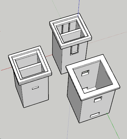
With a bit of tweaking and some test prints, the design that has worked the best includes the outer shell (bottom right) and the inner shell (left). Inside the inner shell, I'll place a single LED light in each chamber. These will be from some of the leftover WS2812b strip I had left over from the Christmas Lights display. These are thin and stupidly bright, so they'll penetrate white plastic fairly easy for this project. I'll also print something of a paper face (maybe a transparent inkjet sheet in future) and do some testing. At the bottom of the outer shell will be a Push button. The 'spring' mechanism in the button will push back on the plastic returning it to the off position and those clips will prevent the button from pushing straight out again. After 3 test prints, and some adjustments to the position of the holes and clips, I'm pleased with the result.
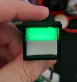
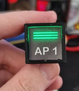
With a bit of tidy up, a transparent sheet and better paper - these switches will fit nicely in the design.
Rotary Encoder with Push and Pull Action
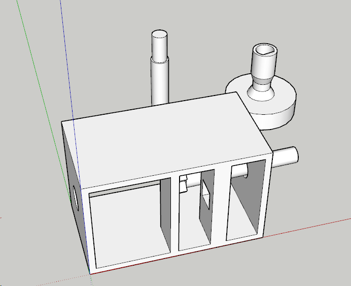
This one was a little more complicated, and a design I'll probably work on - possibly with Cherry MX switches (or clones there-of). These rotary encoder clones are plentiful on YouTube with plenty of ideas. I can't say I'm bringing much new to the table here, only that I'll be designing these to fit in the cockpit I intend to build. This one took a few more goes at the design but the concept is again fairly simple.
The Rotary Encoder will have a push button. If it didn't, I could still achieve the same with a second Push Button but let's not waste what's already available. That leaves the pull action that will need to be activated somehow. With a loose fit on the encoder - tight enough to turn, loose enough to pull, I should be able to build a mechanism that will - when pulled - activate a push button inside the container. Finally - a stalk that will allow the rotation to occur will be required so the user can set their intended Speed, Heading, Altitude or Vertical Speed.
This took a few goes to getting the position and wheel size right. With a digital calliper, this makes the job easier and to fine-tune it, since it uses about 1m-2m of plastic to print any of the components, I figure it's easier to print, then measure with the calliper as to what I need to change.
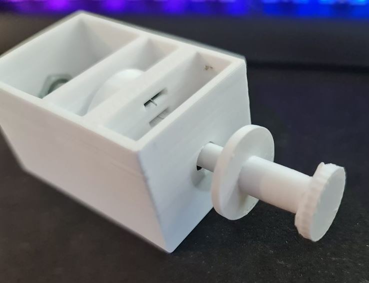
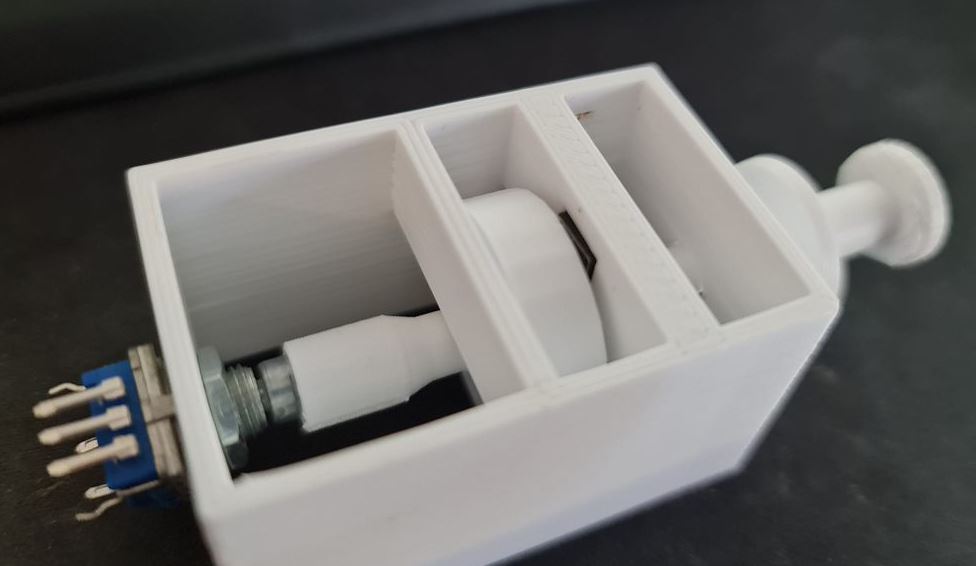
Success! The action works, to a point but the "pull" button is probably not as nice as it could be. So there might still be further modification here before it goes live. Many others use either momentary toggle switches or the larger 12mm square buttons. I have a draw full of different sizes, so we might try something in that space before settling, but definitely some promise here.
For the 100/1000 selector, I've got a few choices in microswitches or toggle switches to try, but these'll come in a future post.
A320 FCU Panel
In designing this one, I note there's a severe lack of vector-image importers for Sketchup Make 2017. My go-to vector tool for years has been Adobe Fireworks which last received an update around CS6. I have a fairly old version of the product but I'm proficient enough in it that vector images are straightforward for me. After some research, I estimate the size of the panel to be 260mm x 90mm. This means that my 200mm x 200mm bed isn't going to fit it all in one. I could do it horizontally if I had the right supports, but I've not yet been successful on my 3D Printer in doing that.
In Fireworks, I prepared a 2600px x 900px vector image and exported it to a format that through some online conversion tools to some pretty legacy formats, got a vector file that I could import into Sketchup. It's not a pretty workflow by any means, and something that probably requires a dedicated post when I can iron out the nuts and bolts of it in something digestible. This Vector file is layered so those colours etc... are visual layers rather than anything particularly useful.
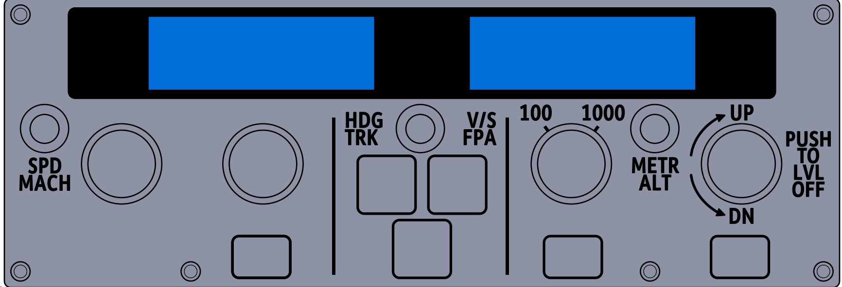
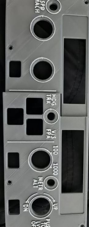
I mentioned earlier that I'd use 2x 1602 character displays and those have been drawn in here instead of the 7 Seg display I'll do at some point in the future. I had to increase the text size to the 5mm in height as identified in the previous post so that it would be legible on the printout. After importing the vector file into Sketchup, the next step was to determine where the 'cut' line will be. I decided to do that on the left part, and straight up the middle of the LCD.
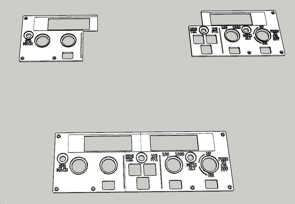
So... now the hard part - determining the best offsets. I settled on 3.5mm for the standard height and an extra 1mm for the text and outlines (which will be painted white after print). So that's what I did. I loaded the printer with some Grey ABS plastic and out comes two pieces albeit slightly warped.
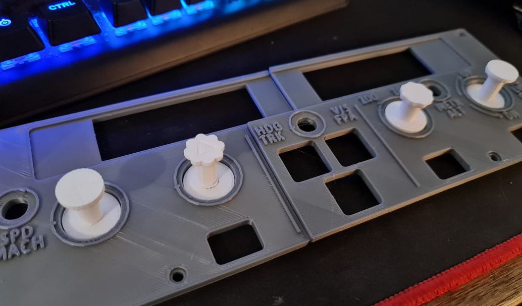
At this stage, I'm pretty happy with how it's coming along, and borrowing a tip from Heli Mech's fantastic video on building similar for a Boeing 737, I bought myself a white paint pen and painted the raised text. And I must say, the results are brilliant - for a 3D Printed job.
Building a Custom Flight Controller for an Airbus A320
Continuing on from my Christmas Blog Post series, this one might very well be the start of building an A320 home cockpit but I make no promises here. One might even call it ramblings of a software developer who has discovered the hobby of 3D printing.
A trip down memory lane...
Among my earliest childhood memories around the Amstrad CPC6128 is one of my favourite games - Acro Jet. It's not a particularly interesting simulator to retrospect on, but the mind of a 4-5 year old can be quite powerful. Neither were F-16 Fighter for the Sega, Top Gun on the Nintendo Entertainment System, and any of the other many flight games on early 8-bit computers and consoles. Fast forward some 5 or 6 years and Microsoft Flight Simulator for Windows 95 was the new hotness. Armed with the Australian Scenery Pack, one could now fly under Sydney Harbour Bridge and... that's about it. Suffice to say, the complexities of aircraft never really hit home - nor could I ever land the planes, no matter the tutorial.
While at university, I saw Flight Simulator X in the bargain bin at one of our common game stores. It was the Accelerated pack, with manuals and all the glossy artwork. In there were several airliners and even though Melbourne Airport was pretty plain, it certainly resembled it more-so than the earlier games. What really enticed me to look at it was the multiplayer aspect - having the ability to be ATC or communicate with someone playing the ATC role. I would go on to play on and off for several years learning bits and pieces - but never taking it too seriously.
Some time around 2014, I had come across some YouTube videos on an Airbus A320 modification for Flight Simulator X. I hadn't looked into Prepar3d or any of the other flight simulators at the time, but this video would describe in detail how to do a cold start, key in your flight path, fuel planning and had some pretty impressive sounds and realism - compared with the stock A320 anyway. This got me interested as it was presented in a very palatable way. Checklists, flying and landing. I would soon after buy the aircraft and learn how to fly the A320 and have a lot of fun doing so for many years to follow. I've been through other simulators as well, including the defunct Flight Sim World, but suffice to say up to the Microsoft Flight Simulator 2020 launch, it's a plane and game I would return to time and time again.
When Flight Simulator 2020 finally released, I had a few weeks to play before my son was born. It was incredible. The stock aircraft were pretty well featured, if not a bit too easy to fly and the scenery was substantially improved - particularly for Sydney Airport (I'd purchased several airports over my time in FSX to improve realism). But... when you start building up those flight hours, get random crashes - it can leave a sour taste behind. Enough at least that I hadn't really played it for over a year since picking it up recent weeks again.
Some 100GB update later, and I note that most of my modifications have been removed, broken or replaced and unfortunately it felt like I was at step 1 all over again (this game has a serious problem in having many tools to modify the game). I remembered somewhere along the line, an open source effort to replicate the Airbus A320 was underway and thought I'd go and check it out. This didn't go so well - involving a total re-install of the game at a further 150GiB. After getting it all up and running again - with the A32nx mod installed (and of course, with a few liveries) - I'm ready to check out where I left things.
Comparing Flight Simulator X (and Aerosoft A320 mod) to Flight Simulator 2020 (and A32nx mod), you'll immediately notice a few things:
- The graphics in FS2020 are incredible compared to FSX - the scenery, motion, etc... feels a heck of a lot more realistic.
- The camera itself is also tilting, I guess just as your head would in a real aircraft.
For #2, this presents a real problem when trying to set any of the aircraft's flight control unit controls - because as you're trying to set an altitude while scrolling your mouse wheel, you may - due to motion - start changing heading, turning off controls, or setting your vertical speed for a nosedive. Suffice to say, this level of "realism" is completely useless for functionally while playing the game.
I've always wanted to build a home cockpit of sorts - there'd be a number of caveats of course. It would have to be compact and modular enough to store away when not in use. It'd also have to be for an aircraft I fly a lot. I'd want it to be familiar enough - but no need to be a perfect replica (I'm not a pilot after all, this is purely for fun) and I'd have to have fun building it as well. Suffice to say, the issue of motion annoys me so much that turning it off removes that feeling of realism so that really leaves me with building a modular set of flight controls.
Building a home cockpit is as old as Flight Simulators themselves, so there's a lot of material around on how to build one. Two of my favourite ones include The Warthog Project and Heli Mech who builds a Boeing 737 cockpit. The latter channel goes through how to build a lot of panels and components a number of different ways and his style has given me a few ideas on how I could similarly approach an Airbus A320 variant - at least in appearance. Over time, I'm sure I'll be adding a CNC machine to my collection but until then, I want to exhaust what it is that I can build using stuff I already own before investing in more garage clutter.
What can I 3D Print?
Heli Mech recently released a video using mostly off the shelf components and some 3D printing on a printer that has a much larger print bed than I do. It would be fairly easy to copy this design and Airbus-ify it, but if at all possible - I'd want to try and get it backlit (this design doesn't) and using custom components to mimic the Korry switches instead of using the KD2 buttons this guy uses. There are several videos on YouTube that make use of Laser cutters and Acrylic to cut out 3 plates - usually a White layer, and a couple of transparent layers that will be painted and etched into giving a professional looking finish to a panel. To get the equipment to do this will set you back a good $1,000 after all is said and done - so to start out, I'd like to see how far I can take this particular project to get an acceptable result.
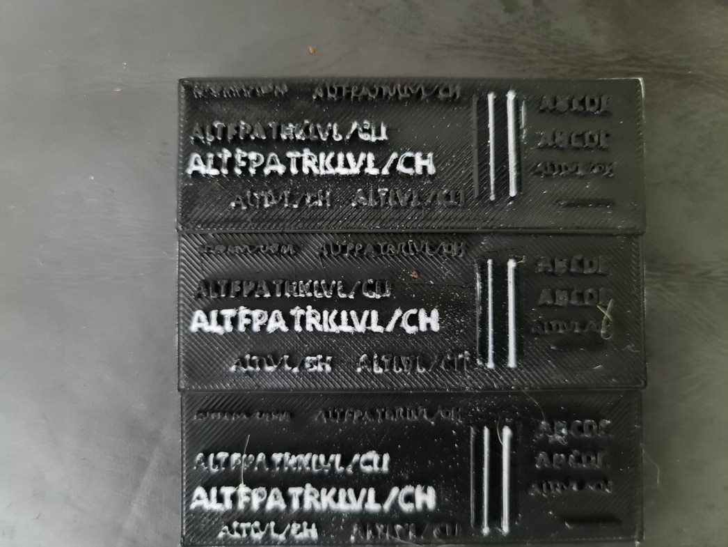
To get started, I really need to see how I'm going to get light through plastic. I begin by designing a 90mm x 90mm canvas at different heights, with text all over them to see what might render well. I've chosen variations between 2mm and 5mm - understanding that 5mm is going to be far too large, but if the text is legible - this might be a trade off I need to make. I then load this into the 3D Printing software and take a look at how the layers are going to print. Obviously the smaller text is going to be tricky - but with a calibrated printer it could be made to work (after the 6 months it's had pushing out Christmas decorations, I'm sure it's anything but level at the moment).
Using some scrap white filament, I'm printing out at 100% infill as the light will need to "push" through and something tells me that light isn't going to be too happy if it's not dense enough. Also - this isn't using transparent filament, it's an opaque white - so no doubt thickness and some seriously bright lights will be required here. Lucky I just finished a project with leftover LED strip that will run super-bright.
After printing, I'll need to use some paint. From the Christmas lights project and the PVC painting, I have some Rustoleum 2x paint - the same as The Warthog Project uses in his example, so fingers crossed at this point that i'll be able to paint that on, use a file and scrape back some of the paint. The result is... not good at all. No light shining through, but I did finally get to an acceptable and legible height. 5mm to be precise is a good height to be totally readable and work with paint being scraped back.
Anyway - that's it for today. I'm going to try and keep these blog posts a little shorter and more frequent as I go. I've already got some working examples of Korry switches (that work) and plenty of gear arriving (potentiometers, rotary encoders, 7 segment displays) - so hopefully within the next couple of weeks I'll have some kind of prototype up and running to improve the flight simulator experience.