Links
Tags
Building a Synchronised Christmas Lights to Music Display - Part 4
With only seven weeks to go, the pressure is on to get all the gear on the house in the next two to three weeks. The same "90% of the work takes 90% of the time, 10% takes the other 90% of time" statement often given to IT projects rings true here too. There has definitely been a lot of work done, but mostly in the non-visible areas of the setup.
The Singing Faces
One would expect that the star of the show will be the singing faces. After all, seeing the singing faces is what got me into really wanting to do this in the first place. Suffice to say, I finally got enough cabling in to start testing what multiple props together looks like and the result is great.
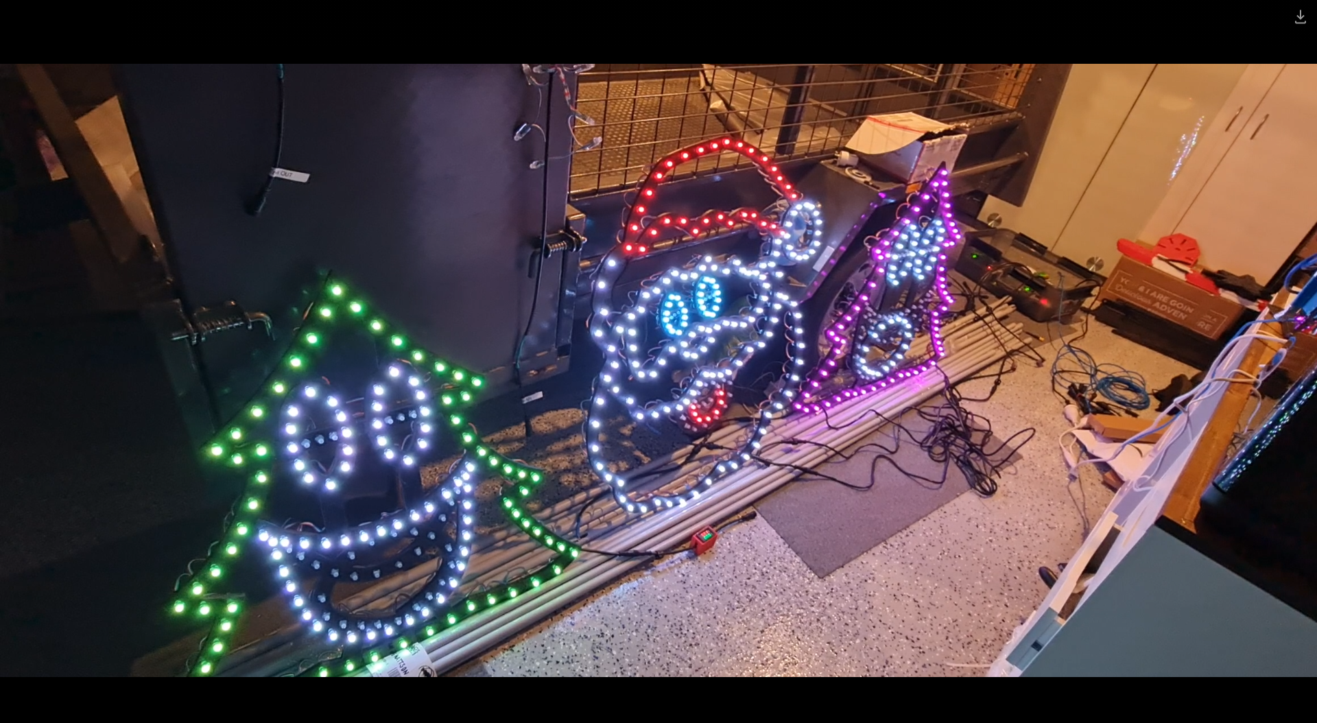
This was certainly something special to see - the props that I'd been working hard on are finally doing exactly what I asked them to do. It's the same sort of satisfaction one gets out of writing code that "just works" - but this felt different. Perhaps the last time I felt this level of accomplishment might stem all the way back to 2016 during the Tour de France live racing project I was part of. Unfortunately it was also short lived when a second sequence I launched caused some significant flickering and colour changes that I thought I knew the answer to.
Now the problem when you watch several hundred YouTube videos on the trials and tribulations of lighting displays, you might be forgiven to thinking you know the answer to any number of problems you may experience. The obvious answer to me was power injection - but I had a T Junction between each of these props, so that shouldn't have been a problem (you can see in the image above the little red volt ammeter box I made in the previous post). While there was an expected voltage drop, the power injection should have absolutely compensated for it. In fact, I even set the brightness from 30% up to 60% expecting a number of pixels to go red (first one to light in a chain) but nope - the flickering didn't seem any worse or better.
The next thing I tried was to swap over the power injection wires in case I had butchered something in the wiring process. I have a collection of 2 pin and 3 pin cables - so swapping these out might also help. Nada. Changed ports on the Power Distribution modules in the power boxes - still the flashing exists. It was getting late so I gave up for the night only to revisit thinking that maybe it requires a signal boost. I'm still not sure why I thought that'd be necessary - after all, each "pixel" should 'regenerate' the ws2811 signal relative to ground so perhaps that was it - but again, power injection should fix that. Several other fixes later, and I tried to work out why one sequence worked and all of the others didn't. Honestly I should have spent more time on this aspect than the others. After watching a few more videos about how the WS2811 signal works (keeping in mind I don't have an oscilloscope), it would appear that if I simply changed the number of output pixels, the flashing would go away (albeit the left hand tree wouldn't light up at all).
Years of problem solving suggests go back to basics and find the odd thing out. The main difference here is that one sequence worked and the other didn't. When I disconnected the left tree, the middle Santa still flickered on that particular sequence so maybe there's something to do with the controller or that sequence. Now, I've been sequencing at 40fps "just because" and never gave it much thought as to how the data would get to the pixel to light up correctly. The 40fps means there's 25ms to process all the data required to light up some 800 pixel x 3 LEDs per pixel. That leaves around 0.0104ms or about 10 microseconds per frame (or 30 microseconds per pixel). So... if you have 800 pixels, and your controller can't quite push 30 microseconds per pixel, you're going to get some corrupted data. In this case, that corrupted data might very well be within lights towards the end of your 'string'. So armed with this thought, I changed the port to rule out a dodgy PWM pin, and sure enough - at 40fps, all three props lit up perfectly and all in sync. To rule out the controller board, I also tested another Raspberry Pi and sure enough - that worked fine on both ports. So yay - on one hand I resolved the issue and on another - I've got a Raspberry Pi 4 that can only push around 400 pixels at 40fps due to something not quite right on this one PWM pin.
Power Distribution
I touched on power distribution last time, but suffice to say I now have two power distribution boxes set up - one for the roof to control the LEDs on the upper half, and one for the ground to do the LED strips, light up props and matrix.
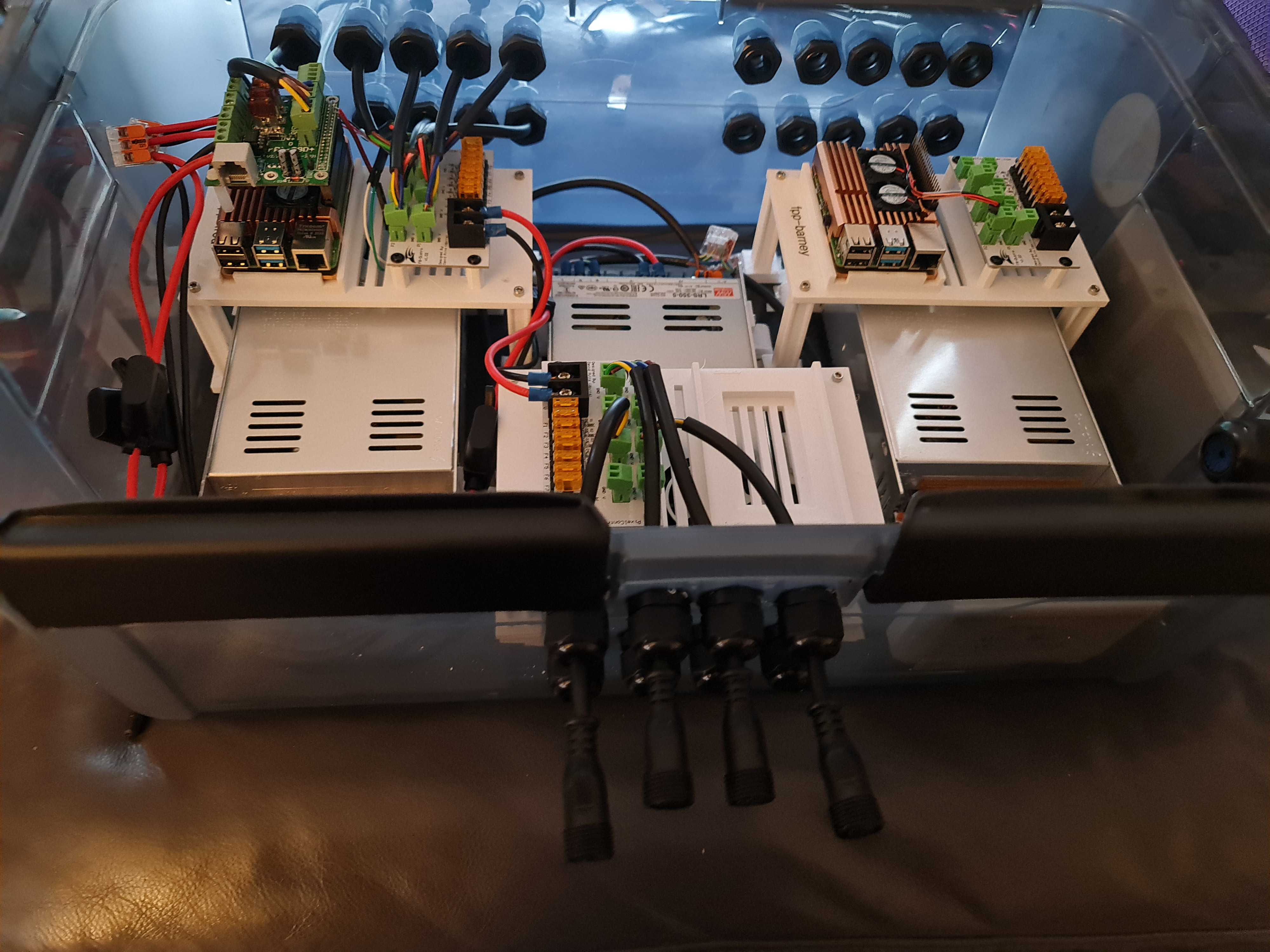
I won't spend a lot of time posting about it - there are plenty of nicer boxes on YouTube and Facebook for this sort of thing but the basics of this setup include:-
- Raspberry Pi 4 with RPi-28D+ capes to run 800 pixels per port (see that flickering post above).
- An 8 port Power Distribution Board
- Either 12V or 5V Power Supply depending on which side of this box I'm plugging stuff into.
In addition, there's a Cat6 socket that plugs into a Ubiquiti Flex Mini switch that's USB-C and POE Powered (yay! found a use for another draw hog) - so these will work nicely under the roof line. To help with some electrical safety here, each input and output is 'fused' to their correct rating - the idea being if we get a short, we'll reduce the risk of something burning.
That's probably all I'll say about this - I wouldn't want you taking electrical advice from a software developer.
Building the PVC Matrix
Ok - so here's an interesting one born out of some ideas borrowed from this video. This is going to be a 50 x 20 pixel matrix cut into 2.5m sections and 5cm spacing. I mocked up several 3D Printed designs - which frankly have been useful but a total waste of time (even when printed at 100% infill, the ABS just isn't quite strong enough to hold the PVC Pipe in place. I also didn't have a drill press, so having 3D printed drill guides helped create some kind of straightness although far from perfect. After several hours dedicated to drilling holes into PVC, the rest is down to painting.
The video I mentioned earlier makes this look easy - frankly this is perhaps the most annoying of all the props to assemble. After painting, I've managed to scratch the paintwork pretty extensively using my 'rings' that will hold and space the PVC pipes together. It's also been super time consuming. Doing this again, I'd probably opt to look at some of the commercial offerings - whether that's chicken wire with 5cm spacing and 3D print 1,000 mounting circles or something else.
Anyway - pictures on this one to come.