Links
Tags
Back Plates, Face Plates and Korry Switches for an Airbus A320
With 3D printing comes a lot of trial and error, and those ends of spools you have a few metres left on certainly come in handy for playing about with sizes. I went into printing small components with eyes wide open - you're battling heat, filament width and height, speed and a number of other factors that make printing with plastics quite difficult.
Designing and Printing the Back Plate
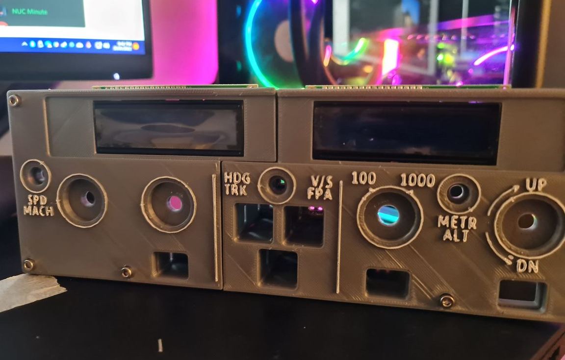
Following on from the front plate last week, I started designing the back plate such that while it'll also need to be split but this time into thirds. This will help with some stability given there's only 6 holes to loosely match the design of the real thing. Similarly, I'd need to ensure the LCD screens would fit in place and Rotary Encoders will have something to grab onto. The holes themselves for holding the Korry switches in would need to be a bit smaller as I had originally planned to have the buttons themselves standalone.
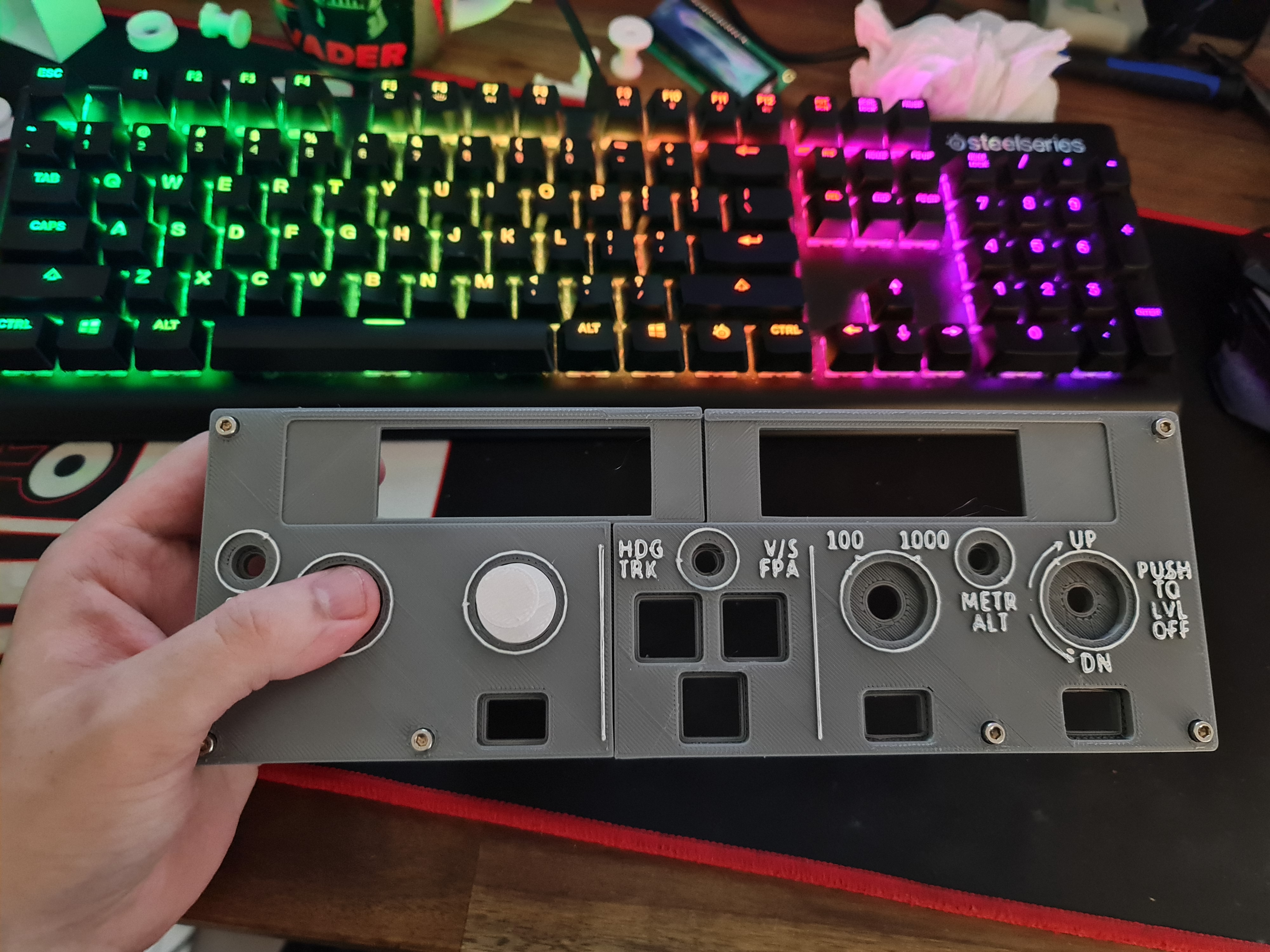
With some printing and brass inserts to hold the faceplate in place, it looks like I'm on the right track.
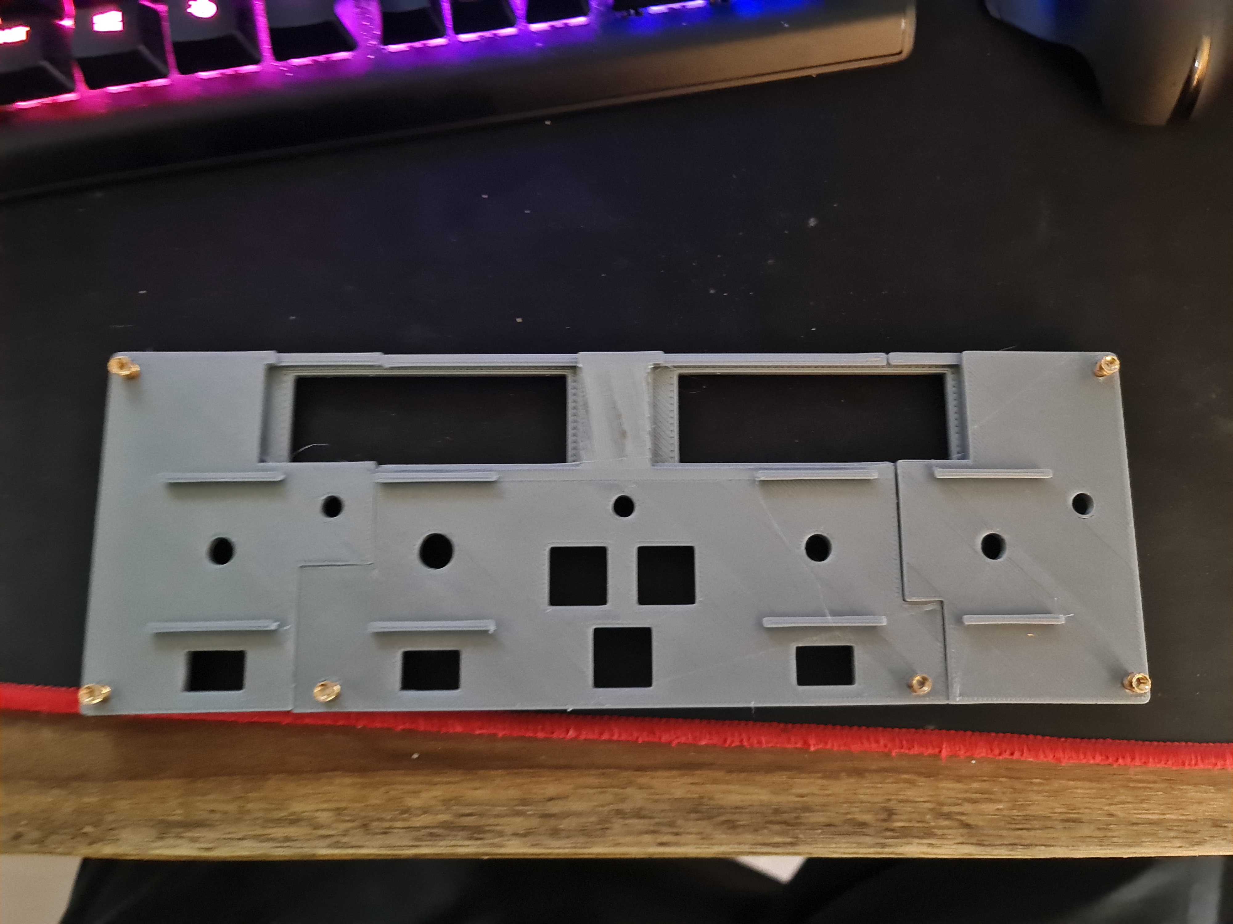
After the initial "awww..." moment, you can start to quickly see some faults. The first is that in this particular design, I'm using 2x 1602 LCD Screens. They have a large(ish) PCB around them. While I had factored in the top, part, I hadn't factored in the bottom part as I was drawing in the Rotary Encoder holds. This is probably where modelling the entire thing upfront would have saved some time...
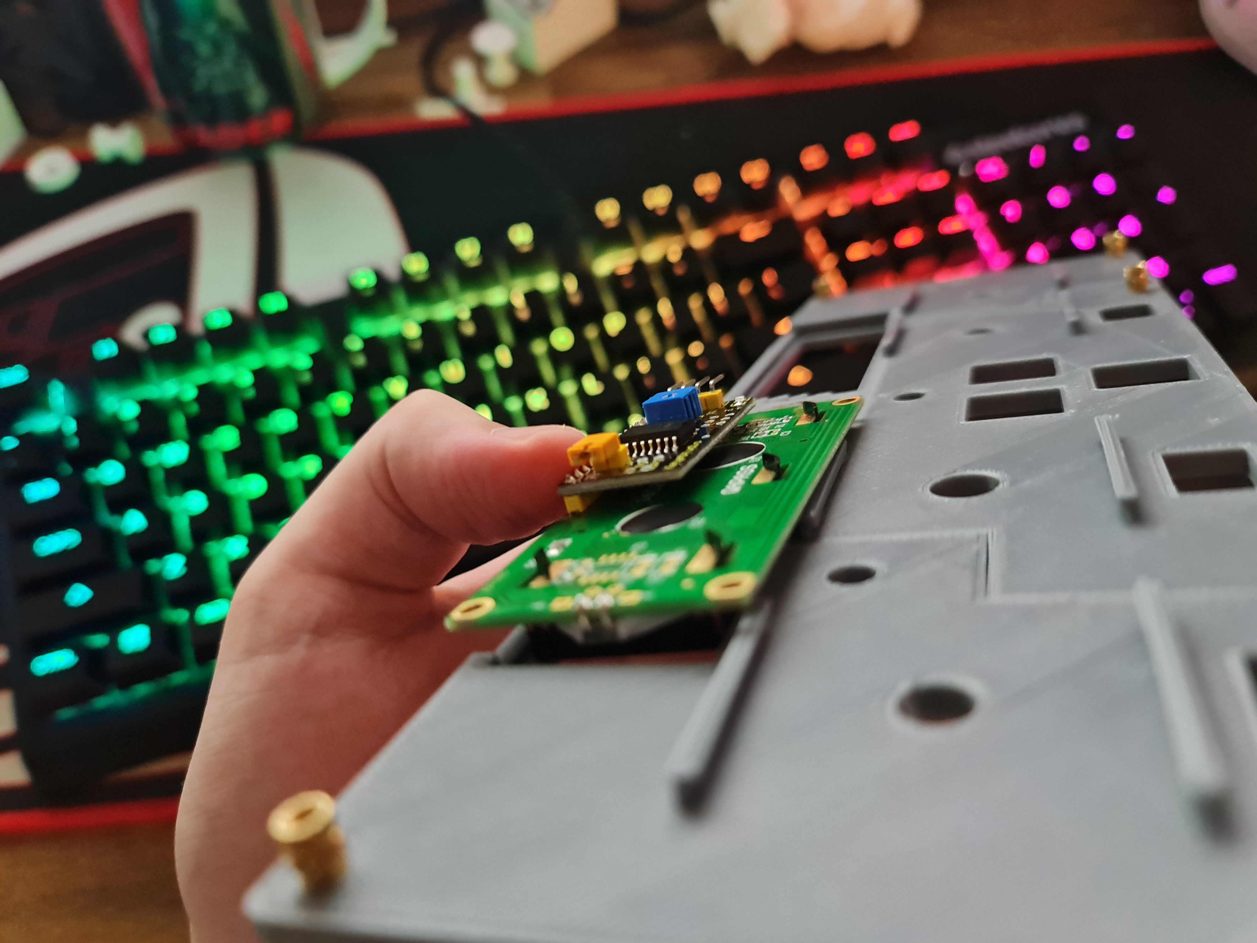
There's also what appears to be a burn mark in between where the LCD screens will fit so I thought I'd better re-level the 3D printer and print again anyway. I don't have any pictures of it, but it largely looked the same and the LCD screens fit flush now. I'd then embark on a journey to build a smaller Korry switch - similar to that tested in the previous post. After several prints, it was clear that the smaller Korry would be too small to fit either a 5050 SMD LED or a 3mm LED bulb so I had to ditch the idea and build the external enclosure as part of the back plate. This process would waste a few days, but we eventually got there. This had to be printed with the button side up, so there was a lot of support material / waste to clear out too.
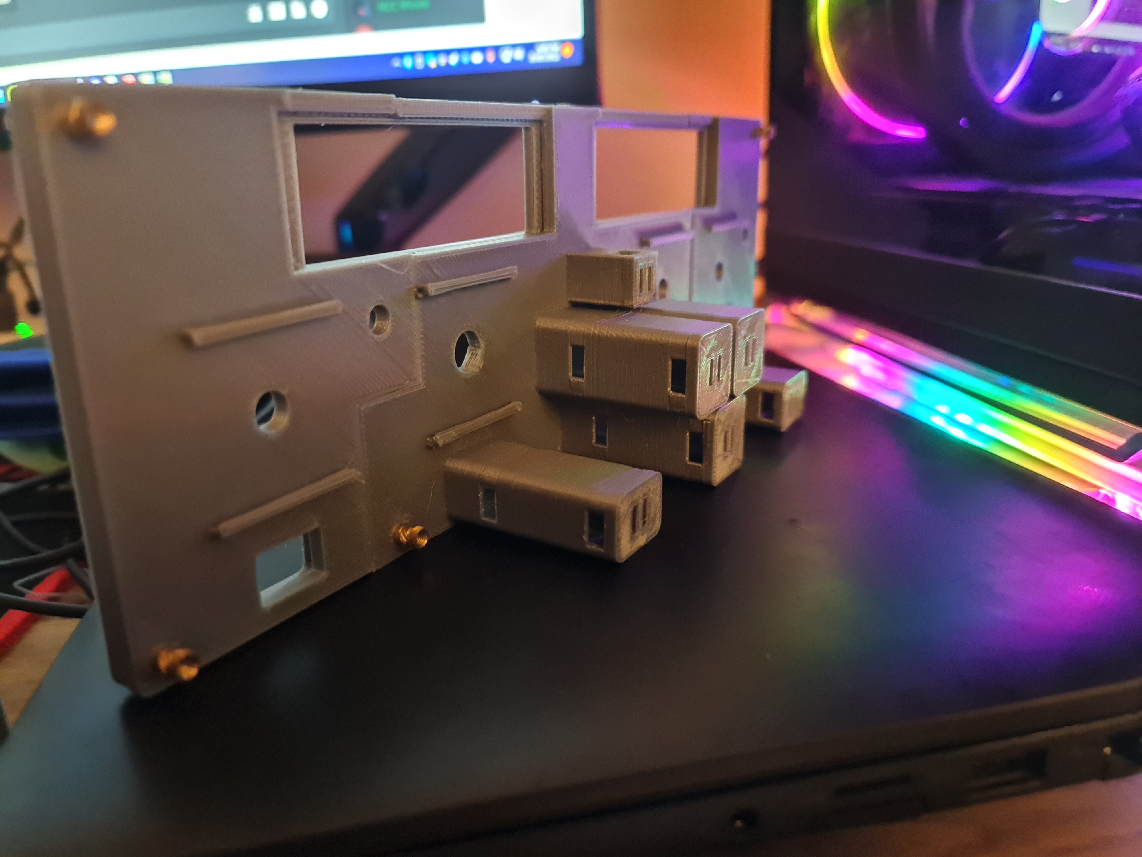
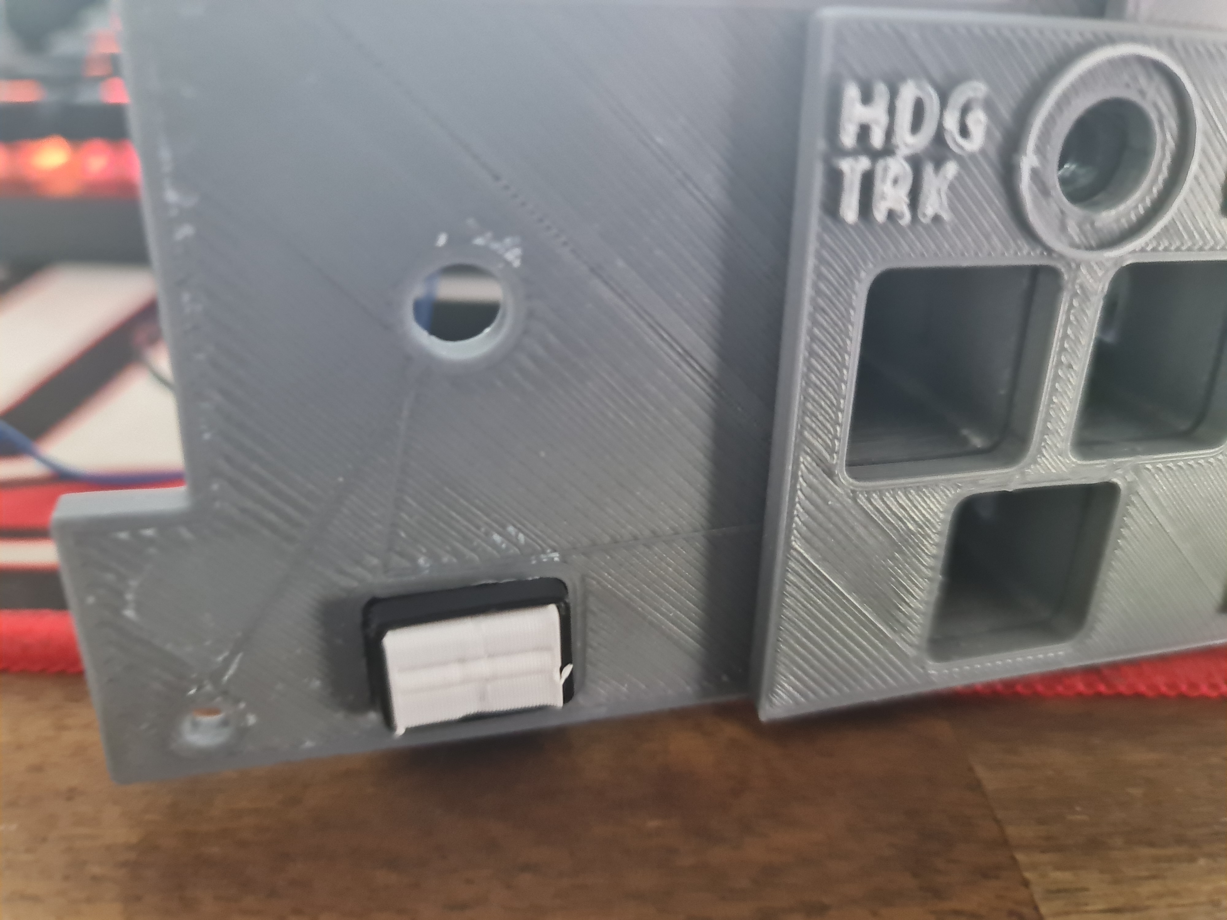
Now that we have an external enclosure for the Korry switches, it's time to test a few possible options.
Finalising the Korry Switch
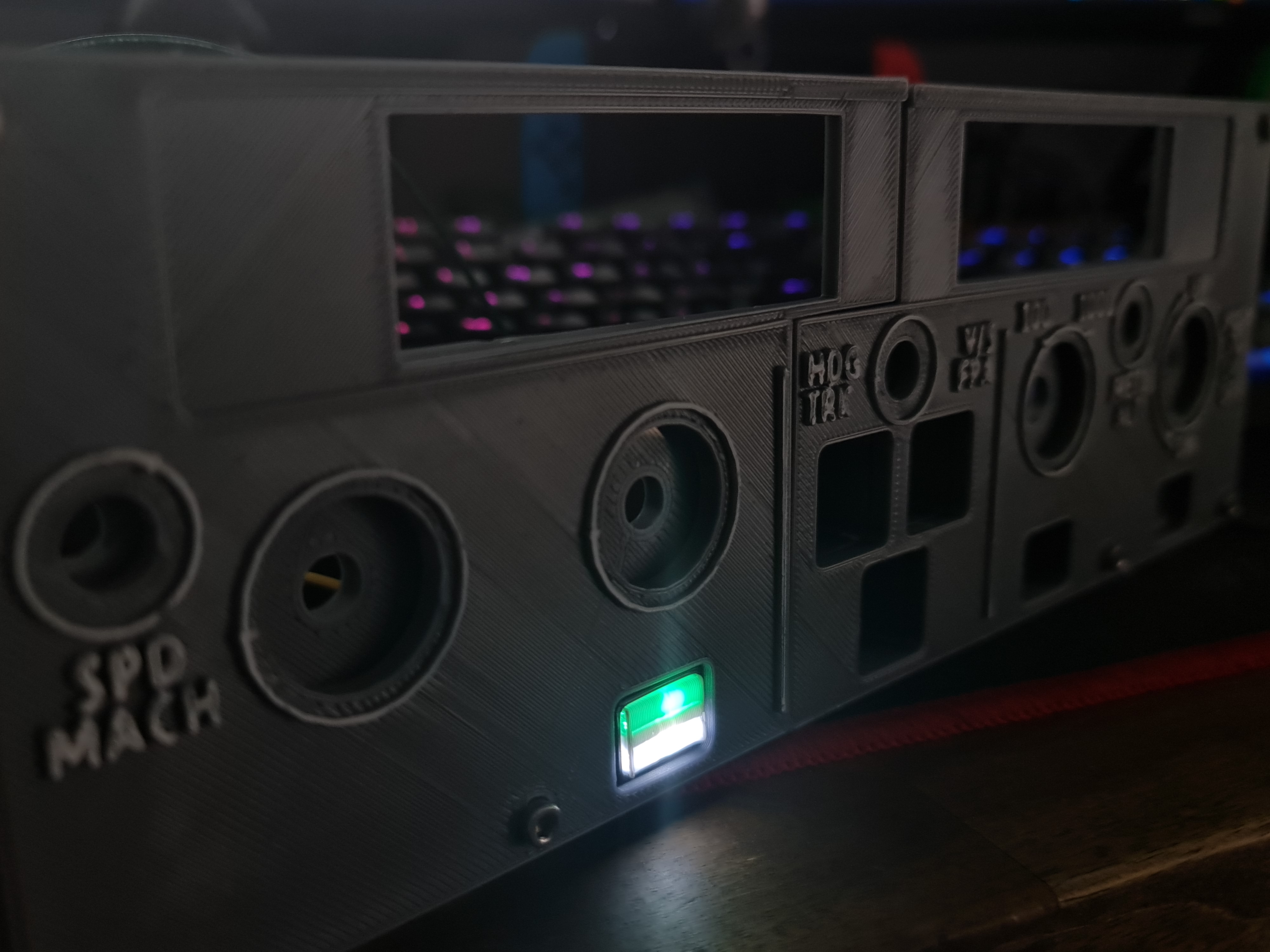
Using the same dimensions as present in the new backplate, it was time to re-do the design. The main challenge and re-do here was getting the right size appropriate for the hole. When working within 1mm tolerances, you tend to fight both the printer and design. After 3-4 goes, we've got a good fit and button action (albeit the buttons themselves are kind of garbage).
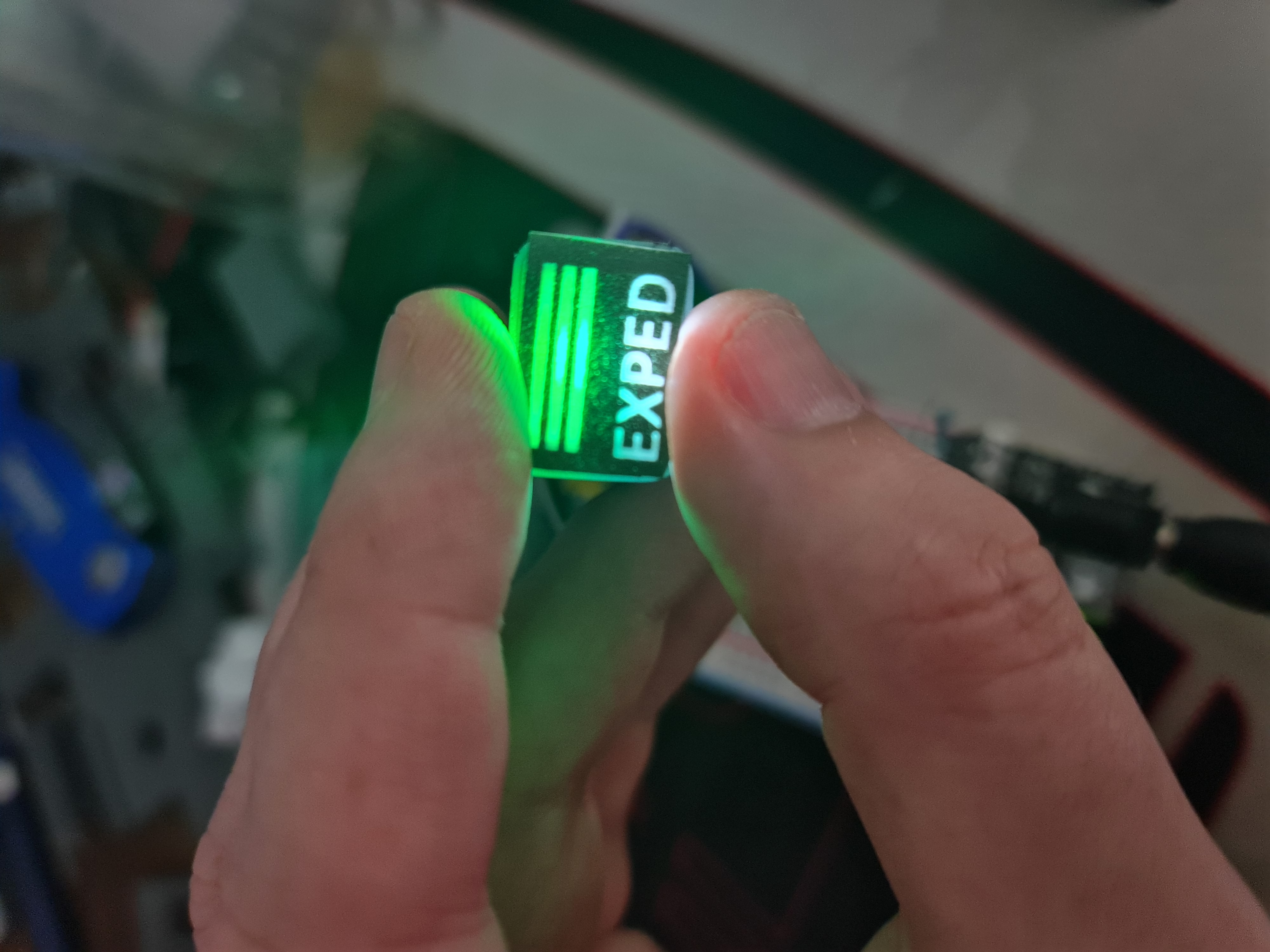
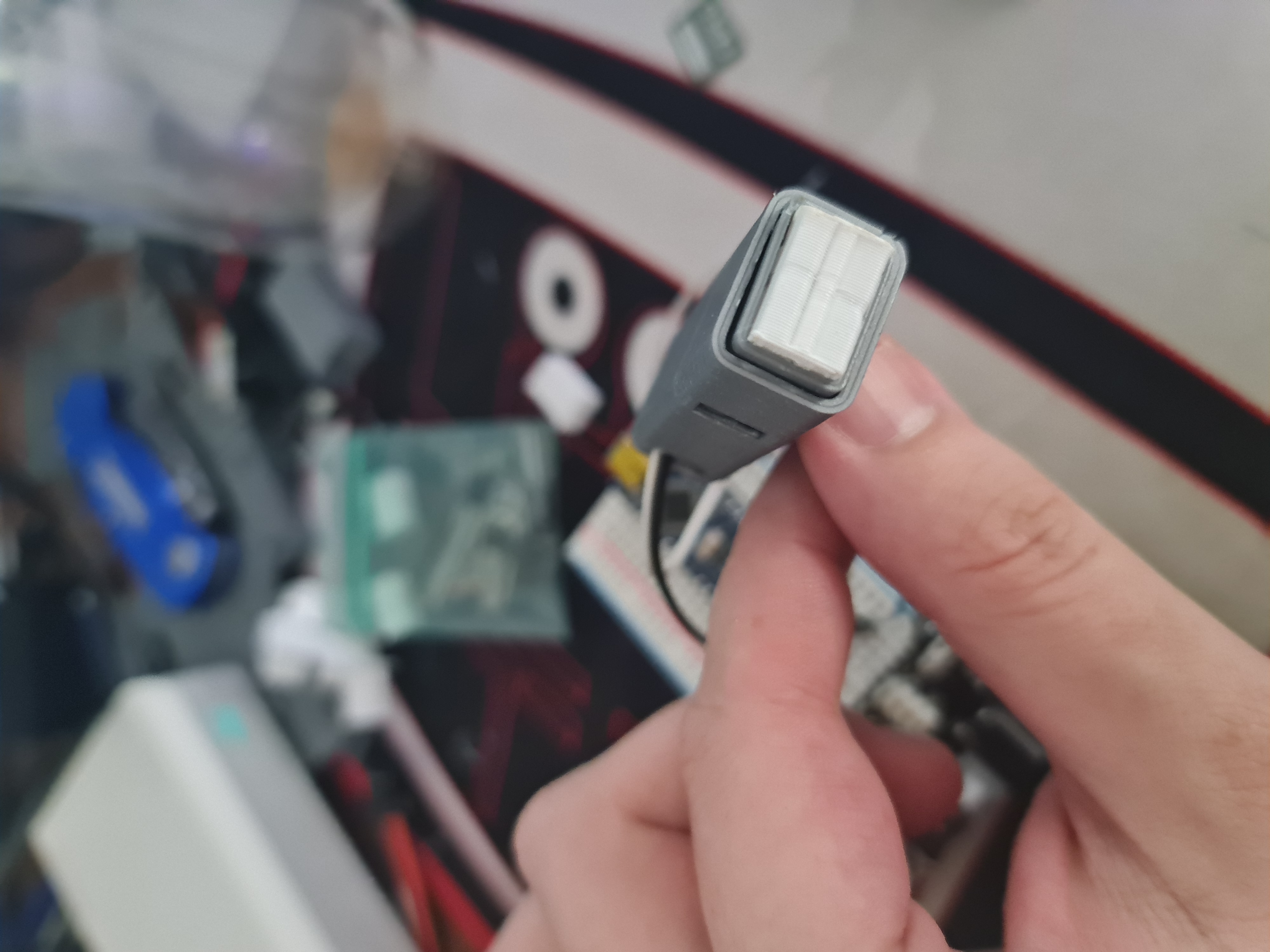
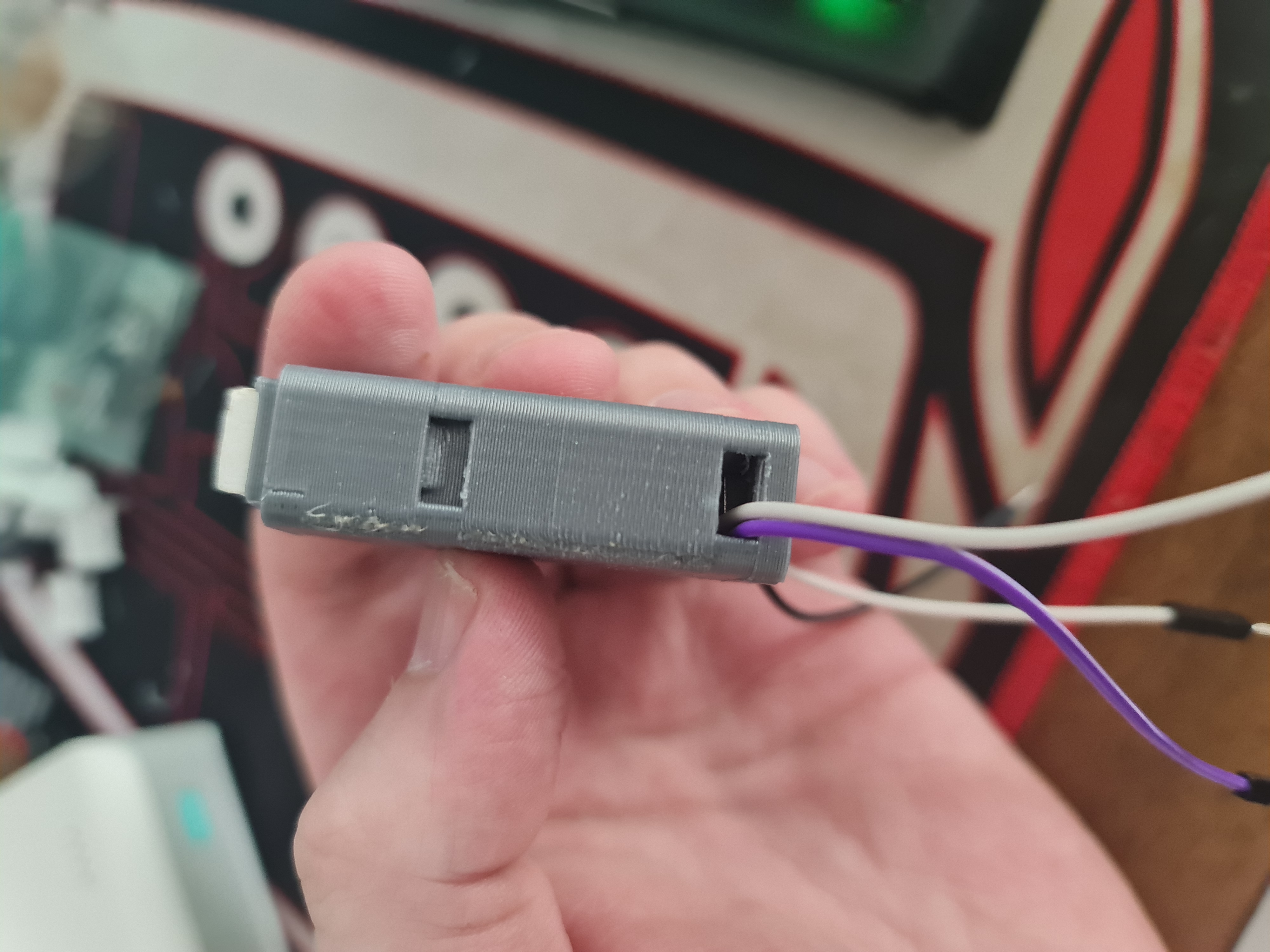
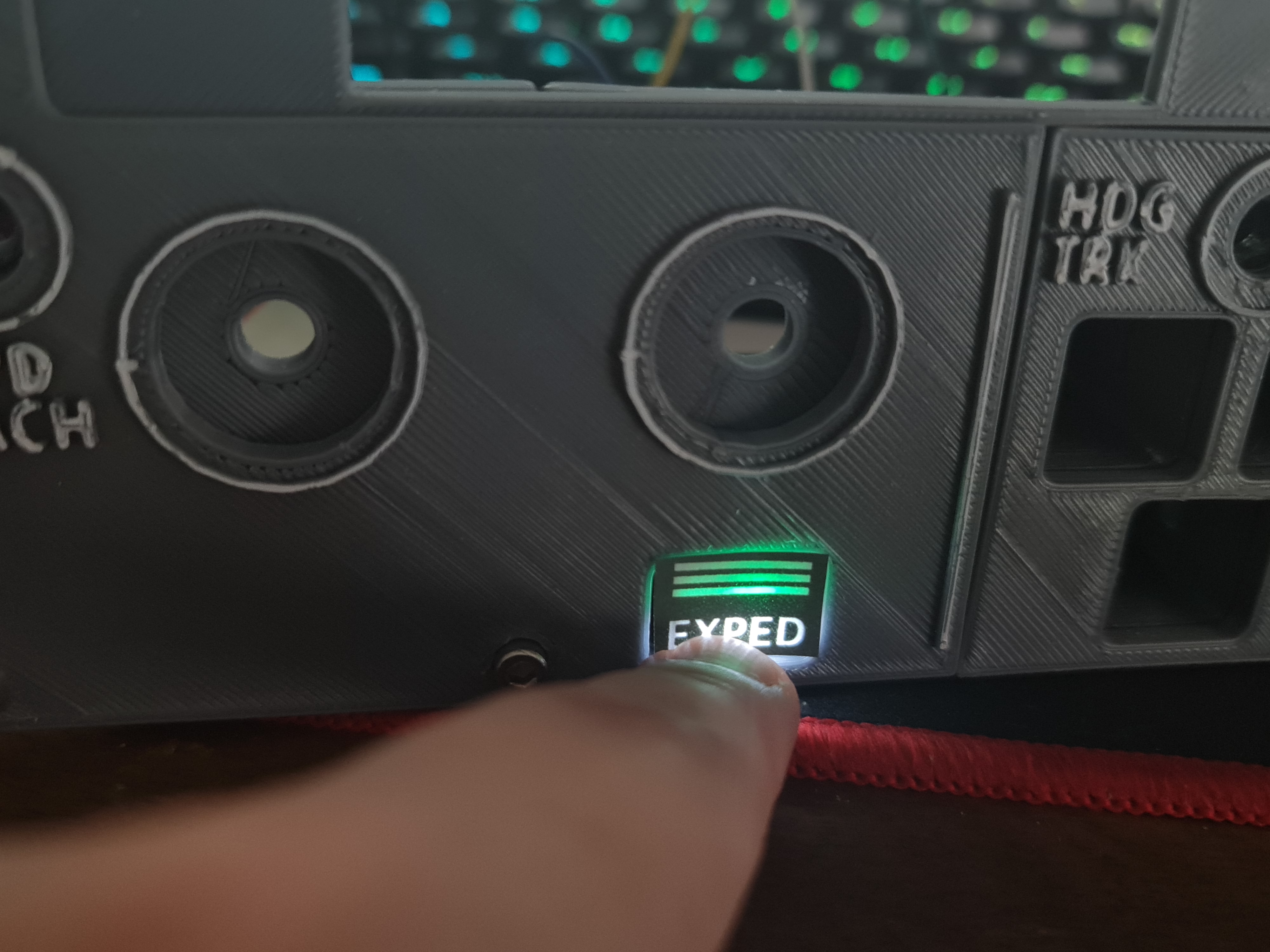
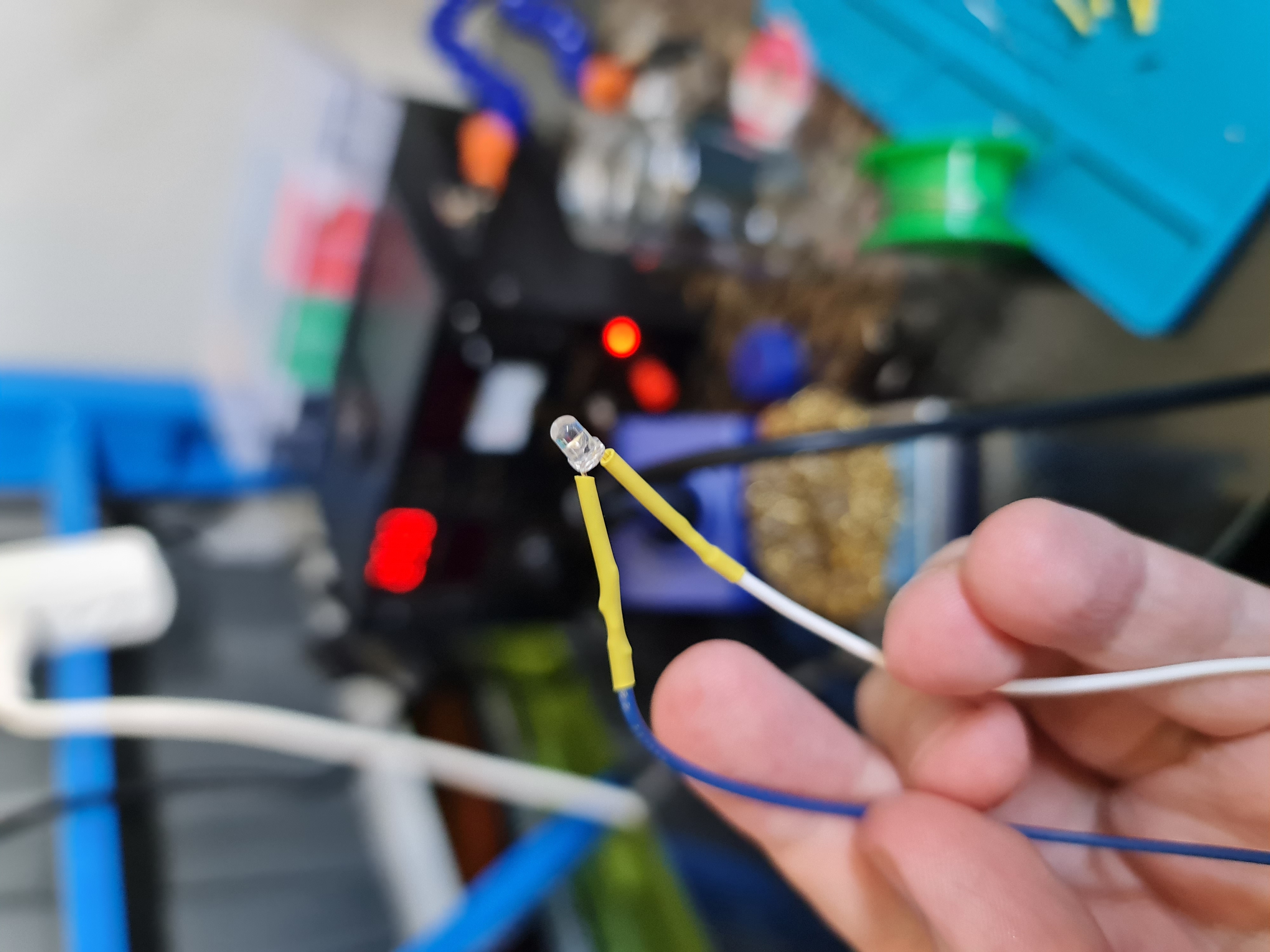
This... took quite a few goes (the diffuser, that is). Inside the chamber is a button and an insert. Green and White 3mm LEDs sit inside a small white diffuser thing, similar to the original Korry design. All that's left now is to solder up a bunch of LEDs, wires and buttons to fit inside of the FCU.
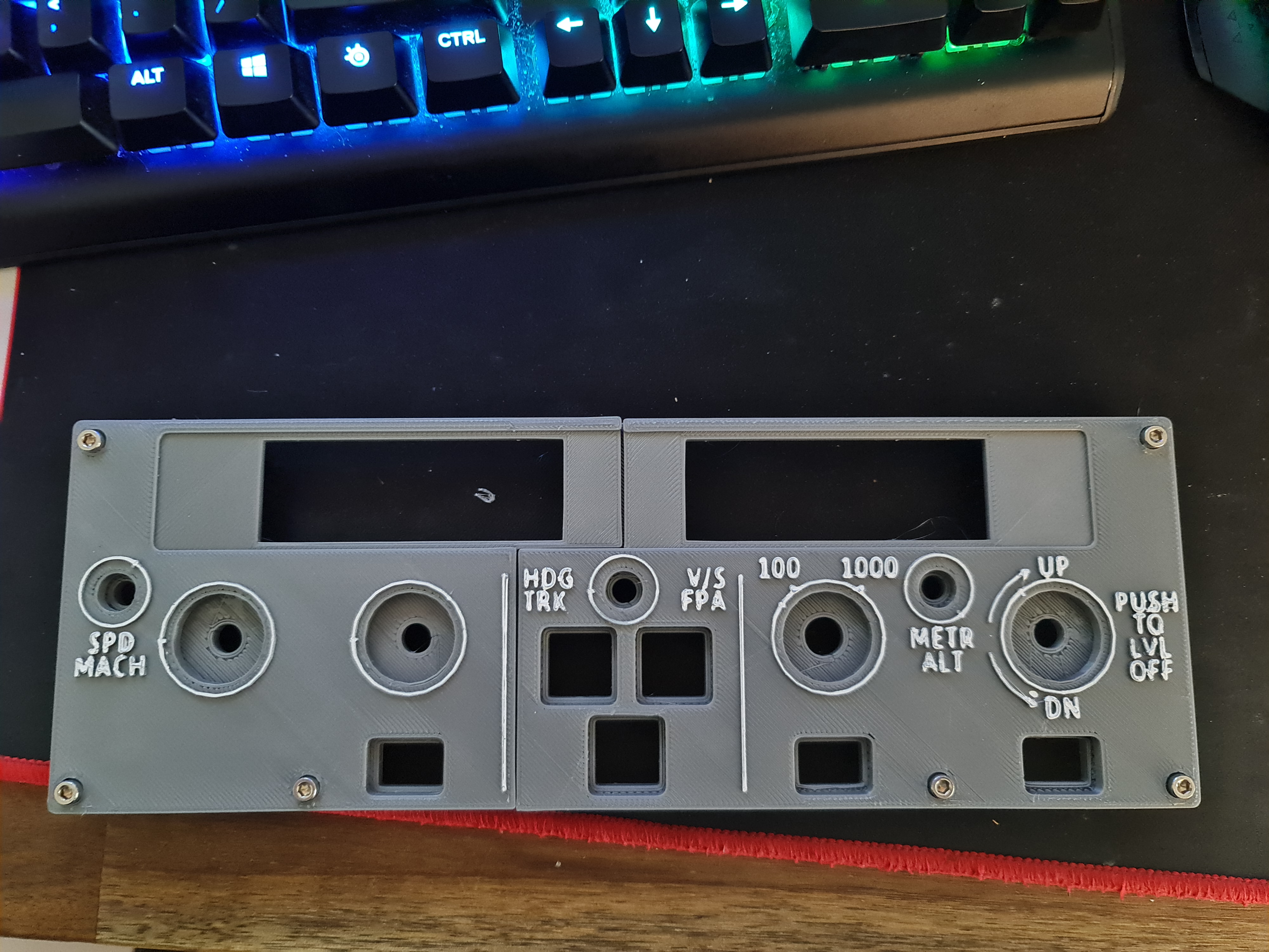
After getting the LEDs all installed and buttons all set up, it's time to put it in the main face plate and the result is pretty good. Still plenty of work to do and some transparent sheets to play with.